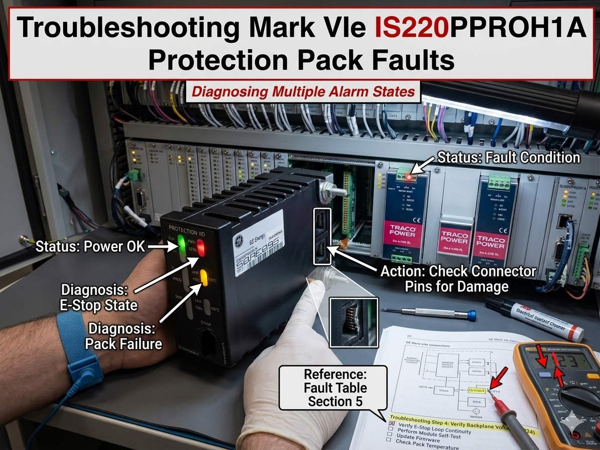
Troubleshooting the Alternating Yellow and Red Status LED on GE IS220PPROH1A Protection Packs
The GE IS220PPROH1A Protection Pack serves as a critical safety controller within GE EX2100 excitation systems and Mark VIe turbine control architectures. During field service operations, engineers frequently encounter a status LED that alternates between yellow and red. This highly specific error pattern typically manifests following cabinet energization, firmware updates, or major network reconfigurations.

Understanding the Critical Alarm State of the Protection Pack
In practical turbine and control systems diagnostics, this dual-color flashing sequence signals a severe initialization or communication failure. Specifically, the module indicates a firmware incompatibility, an internal self-test fault, or a complete loss of synchronization with the master controller. Therefore, field technicians must not treat this state as a minor warning. Because the pack enters a non-operational mode, it cannot reliably execute critical safety trip logic during an emergency event.
Core Value: Ensuring Deterministic Protection in Power Generation
The main engineering value of the IS220PPROH1A involves providing high-speed, deterministic protection processing where milliseconds directly impact asset survival. In hazardous environments like petrochemical plants and combined-cycle power facilities, this module isolates faults before they propagate into catastrophic generator damage. Consequently, maintaining the operational integrity of the pack reduces nuisance trips, prevents overspeed protection failures, and minimizes unplanned outages.
Technical Nuance 1: Firmware Misalignment and Controller Revisions
A frequent catalyst for the alternating yellow and red LED pattern is a firmware version mismatch. This discrepancy usually occurs between the protection pack, the Mark VIe controller, and the master ToolboxST software application. Engineers often trigger this condition during partial cabinet upgrades or when restoring older backup images into newly deployed hardware. While the mismatched module may power up successfully, it ultimately rejects synchronization commands across the dedicated IONet network.
Technical Nuance 2: Maintaining IONet Network and Communication Integrity
The IS220PPROH1A relies heavily on stable, low-latency Ethernet communication via the proprietary GE IONet architecture. Industrial issues like incorrect duplex configurations, unmanaged network switches, or excessive electromagnetic interference (EMI) frequently corrupt these critical data frames. In my professional experience at PLC Pioneer, networks installed near large variable frequency drives (VFDs) are particularly vulnerable. Without proper shield grounding, high-frequency noise causes rapid communication drops, forcing the module into a fault loop.
Technical Nuance 3: Hardware Diagnostics and Internal Watchdog Faults
The internal processor continuously monitors its own memory allocation, circuit temperature, and hardware watchdog timers to ensure execution stability. If the internal startup diagnostics fail consecutively, the protection pack immediately locks itself into the yellow and red indicator state. These watchdog-triggered resets often stem from unstable external 28VDC power distribution or gradual component degradation from long-term thermal exposure. Consequently, the processor suspends safety-critical subroutines to prevent unpredictable control actions on the plant floor.
Field Maintenance Guide: Preventive Steps and Hardware Handling
- ✅ Verify Power Quality First: Measure the DC ripple voltage and inspect terminal oxidation before removing any control hardware from the cabinet.
- ⚙️ Enforce Network Isolation: Route industrial Ethernet links away from high-voltage cables and utilize managed switches to block broadcast storms.
- 🔧 Stop Live Hot-Swapping: Isolate cabinet power completely and freeze controller communications before replacing a protection pack to preserve configuration data.
- 📊 Confirm Revision Alignment: Always validate firmware package compatibility inside ToolboxST before deploying a new module to the field.
PLC Pioneer’s Expert Commentary on System Protection
“Many maintenance departments make the costly mistake of immediately replacing the IS220PPROH1A pack the moment the yellow and red fault pattern appears. However, our field data indicates that over sixty percent of these instances stem from baseline power instability or software handshake failures rather than dead silicon. In modern factory automation, rushing to swap hardware without checking the IONet configuration often introduces fresh synchronization errors and extends your total downtime.” — PLC Pioneer
Experienced Automation Insights: Diagnostic FAQ
Q: What specific voltmeter readings indicate a power supply issue rather than a broken protection module?
A: You should look for an AC ripple voltage exceeding 200 millivolts on the nominal 28VDC bus. High ripple frequently fools the internal microprocessor into executing repeated watchdog resets, which generates the alternating LED pattern even on perfectly healthy hardware.
Q: How do we safely force a forced firmware alignment if ToolboxST refuses to talk to the flashing pack?
A: You must isolate the target module onto a dedicated single-node network directly connected to your engineering workstation. This isolation prevents packet collision and allows the low-level bootstrap loader to accept the correct firmware override image without interference from the main control architecture.
Q: Does environmental vibration contribute to this specific dual-color flashing fault over time?
A: Yes, persistent low-frequency mechanical vibration can gradually loosen the physical seating between the I/O pack and its underlying terminal board. This micro-separation interrupts the high-speed local bus connections, forcing the onboard self-diagnostics to flag a fatal hardware communication fault.
Real-World Application Scenario: Preventing Steam Turbine Overspeed Failures
Consider a large petrochemical refinery utilizing a steam turbine driver for an industrial compressor system. During a routine network switch replacement, improper configuration introduced latency spikes exceeding 15 milliseconds across the plant DCS backbone. The local IS220PPROH1A immediately lost synchronization with the Mark VIe core, safety relays locked open, and the status LED began flashing yellow and red. Because the system instantly flagged this vulnerability, the plant operators safely managed a controlled shutdown, avoiding a catastrophic overspeed event that could have destroyed the turbine rotors.
If you need to source high-reliability replacement packs, update legacy firmware configurations, or bridge your older turbine hardware with modern Ethernet control networks, discover our technical inventory and support resources.
Visit our official resource center for technical guides and hardware support: PLC Pioneer Limited