Troubleshooting ABB 5SHY4045L0004 IGCT Gate Driver Power Fail: Board Repair vs. Full Unit Replacement
In high-power industrial automation systems, the ABB 5SHY4045L0004 / 3BHB021400R0002 Integrated Gate-Commutated Thyristor (IGCT) module plays a critical role. This component drives medium-voltage inverters where switching reliability directly dictates plant uptime. However, encountering a “Gate Driver Power Fail” alarm poses a challenging dilemma for maintenance teams worldwide.
Understanding the Critical Operational Value of ABB IGCT Modules
ABB designed the 5SHY4045L0004 IGCT platform for high-current, fast-switching applications. Consequently, heavy industries deploy these modules in cement plants, mining operations, petrochemical compressors, and marine propulsion systems. The technology combines excellent surge current tolerance with low conduction losses. Therefore, minimizing inverter downtime in these continuous-process industries can save thousands of dollars per hour.
Decoding the Technical Causes of Gate Driver Power Failure
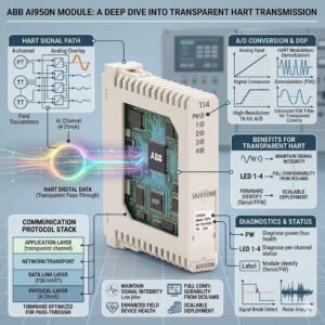
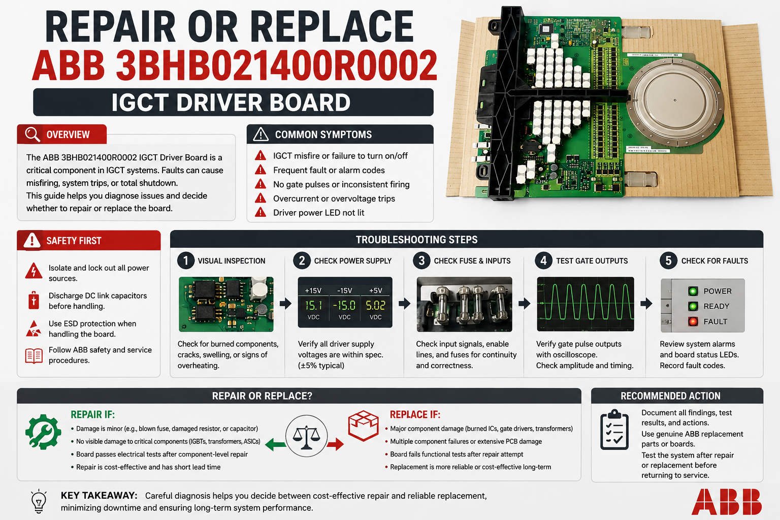
The “Gate Driver Power Fail” alert indicates that the gate unit cannot sustain the voltage required for proper switching. Frequently, internal component degradation causes this issue rather than a catastrophic failure of the semiconductor die itself. Aging electrolytic capacitors, degraded DC/DC converters, or unstable auxiliary power paths often trigger the fault. As a result, the IGCT might operate in a partially enhanced state, which accelerates thermal breakdown.
Analyzing Thermal Cycling and Board-Level Integrity
Field data from heavy industrial environments shows that thermal stress significantly impacts driver board lifespan. If the power failure alarm appears only after a thermal soak period, look for cracked solder joints. Moreover, high ambient dust and vibration in steel mills accelerate connector degradation between the IGCT and the gate unit. In these scenarios, changing only the board provides a temporary fix rather than a permanent solution.
Evaluating the Impact of Fiber-Optic Signal Degradation
ABB control systems rely on precise fiber-optic link synchronization to control the gate unit safely. A weak optical signal can trick the system into reporting a gate driver power fault. Therefore, maintenance teams must inspect fiber end-faces for contamination and verify the cable bend radius. During motor acceleration, high physical vibration can cause loose fiber connections to disrupt transmission intermittently.
Strategic Checklist Before Replacing High-Value Hardware
- ✅ Static Resistance Testing: Perform insulation and gate-to-cathode resistance checks to verify semiconductor health.
- ⚙️ Optical Power Verification: Measure the decibel loss across fiber links using an industrial optical power meter.
- 🔧 Snubber Circuit Inspection: Evaluate the health of adjacent sharing resistors and snubber capacitors for leakage.
- 📊 Firmware Verification: Match control firmware versions between replacement driver boards and the existing phase-arm topology.
When Comprehensive Assembly Replacement Becomes Mandatory
Sometimes, localized repair introduces unacceptable risks to the wider plant electrical infrastructure. If the fault history reveals concurrent overcurrent events, the internal semiconductor layer has likely suffered structural damage. Furthermore, physical discoloration around the terminals or a previous cooling pump failure demands a full module replacement. Recommissioning a compromised stack with a new board risks an expensive busbar short-circuit event.
Practical Installation Rules for Severe Environments
Preventing repeat failures requires strict adherence to physical installation standards. Always torque all gate unit mounting hardware to exact factory specifications. In addition, route fiber-optic cables completely separate from high-power copper busbars to eliminate electromagnetic interference. Finally, check the condition of the thermal paste and verify coolant flow rates before energizing the drive network.
PLC Pioneer’s Expert Field Commentary
“In my years optimizing control systems, I have noticed that engineers rush to replace the entire 5SHY4045L0004 assembly prematurely. This aggressive approach inflates maintenance budgets unnecessarily. However, blindly swapping boards without checking fiber-optic transmission parameters or clamp circuits invites catastrophic secondary failures. In 2026, predictive maintenance dictates that we validate the power environment before making hardware decisions.” — PLC Pioneer
Decision Matrix for Maintenance Managers
| Fault Condition Observed | Recommended Action Plan |
|---|---|
| Intermittent alarm, no overcurrent history | Replace the gate driver board first. |
| Alarm persists after driver board swap | Replace the complete IGCT assembly. |
| Visible thermal discoloration or burned terminals | Replace the entire module immediately. |
| Prior cooling system failure on the phase arm | Full module replacement strongly advised. |
Frequently Asked Questions
Q: How can field technicians distinguish between a faulty power board and a broken optical interface?
Technicians should apply external auxiliary power to the gate unit while the drive remains safely isolated. If the onboard status LEDs indicate correct voltage levels but the central controller fails to receive the ready signal, focus troubleshooting efforts entirely on the fiber transceiver paths.
Q: What role do aging capacitors play in medium-voltage drive reliability?
Electrolytic capacitors on the driver card smooth out switching pulses. Over years of continuous thermal loading, these components lose capacitance and exhibit high equivalent series resistance. This degradation causes voltage ripple, triggering nuisance undervoltage faults inside the monitoring circuit.
Q: Are different manufacturing revisions of the 3BHB021400R0002 completely interchangeable?
No, they are not always cross-compatible. Later production batches often utilize updated gate timing parameters and improved protection thresholds. Mixing mismatched revisions within the same phase arm can cause asymmetric turn-off characteristics, which unbalances the voltage distribution across components.
Application Scenario: The Mining Conveyor Inverter Recovery
A copper mine experienced repeated drive trips on a primary conveyor system due to gate failures. Rather than replacing the full multi-thousand-dollar IGCT assemblies every time, an engineering audit revealed severe structural vibration. By isolating the fiber cables, re-torquing the driver boards, and introducing localized vibration damping, the site eliminated the nuisance faults completely while saving significant capital expenditure.
If you need to optimize your medium-voltage drive performance or require certified spare parts to secure your plant operations, access our technical inventory today.
Visit our official resource center for technical guides and premium component procurement: PLC Pioneer Limited