Troubleshooting ABB UFC719AE01: Oscilloscope Diagnostics for Phase Loss and Fiber-Optic Pulse Failures
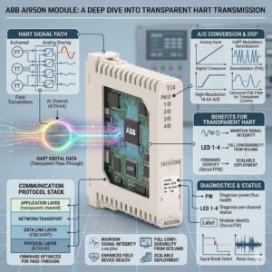
The ABB UFC719AE01 3BHB003041R0101 pulse distribution board serves as a core interface module within high-power thyristor rectifier systems. This vital hardware distributes synchronized firing pulses to power semiconductor bridges via fiber-optic cables. Consequently, it maintains precise firing angles and balanced DC outputs under heavy electrical loads. Heavy industrial sites depend heavily on this board to keep massive synchronous motors running efficiently.

The Threat of Phase Loss in Thyristor Rectifier Control Systems
In heavy industries like steel production and mining drives, trigger pulse failures disrupt entire factory automation architectures. Missing a single optical pulse can immediately stall thyristor conduction. As a result, the rectifier bridge experiences severe phase loss and unbalanced DC bus voltage. Moreover, intermittent pulse attenuation often generates destructive thermal stress inside the Silicon Controlled Rectifier (SCR) long before a total system shutdown occurs.
Oscilloscope Measurement Strategy for High-Speed Optical Inputs
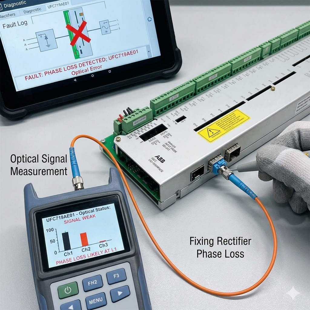
Standard oscilloscope probes cannot capture raw optical signals directly without specialized hardware interface adapters. Therefore, field engineers must use an optical-to-electrical converter module to accurately analyze pulse trains. First, disconnect the suspect fiber-optic cable safely from the UFC719AE01 input port. Next, route the converter output directly into your digital oscilloscope channel. This method safely preserves signal integrity and protects fragile fiber end faces from mechanical damage.
Decoding Trigger Waveforms to Identify Root Cause Failures
A healthy optical firing pulse displays a highly stable, repetitive wave train with a fixed duty cycle. If pulse gaps appear periodically every 120 or 180 electrical degrees, the problem usually originates from upstream synchronization logic. Conversely, random pulse drops indicate physical transmission issues along the fiber line. Technicians must compare these timing waveforms against the main AC phase reference to isolate synchronization errors from board hardware defects.
Overcoming Diagnostic Complexities in High-EMC Noise Environments
ABB engineers utilize fiber-optic isolation on the UFC719AE01 to block severe electromagnetic interference (EMI). Industrial control systems face high dv/dt switching transients, ground loops, and massive magnetic fields near high-current busbars. While optical fiber offers excellent noise immunity, it complicates traditional troubleshooting methods. In many instances, aging upstream optical transmitters cause system faults rather than the distribution board itself.
—
Common Field Issues and Component Fault Matrix
- ✅ Random Pulse Loss: Occurs when the fiber-optic bending radius is too small.
- ⚙️ Single Channel Failure: Typically points to an aging upstream optical transmitter.
- 🔧 Vibration Instability: Caused by loose mechanical locks on fiber-optic connectors.
- 📊 Thermal Drift Faults: Triggered by degraded optical receiver components overheating under load.
—
Safe Grounding Practices for Thyristor Cabinet Maintenance
Improper oscilloscope grounding can destroy low-voltage control circuits and create dangerous ground loops inside excitation cabinets. Engineers should utilize a battery-powered isolated oscilloscope for all live measurements. Furthermore, always connect differential probes when measuring electrical signals near high-voltage gate drivers. Never attach standard grounding clips directly to the control cabinet protective earth in floating electrical systems.
Preventative Maintenance for Critical Fiber-Optic Links
Conductive dust, oil mist, and atmospheric oxidation frequently contaminate ST-type fiber connectors in cement and steel mills. This contamination attenuates light intensity and induces intermittent control system faults. Therefore, clean all fiber terminals with lint-free optical swabs during scheduled plant shutdowns. In addition, inspect the connector faces with a specialized microscope to guarantee optimum optical power transmission.
System-Level Verification Before Board Replacement
Many maintenance teams mistakenly replace the UFC719AE01 board immediately after seeing a phase loss alarm. However, phase errors frequently stem from synchronization transformer faults or Phase-Locked Loop (PLL) instability. Technicians should verify the stability of the main AC synchronization reference prior to hardware replacement. This comprehensive verification prevents unnecessary spare parts expenditure and shortens overall factory downtime.
PLC Pioneer’s Field Commentary on Hardware Compatibility
“In my field experience at PLC Pioneer, replacing a UFC719AE01 without checking firmware compatibility often causes system interlock failures. ABB utilizes distinct optical communication protocol revisions across different generations of excitation cabinets. Even if the physical board profile looks identical, minor firmware mismatches can disrupt critical trigger timing. Always cross-reference your system serial configuration before ordering expensive replacement spares.” — PLC Pioneer
Expert Practical Answers to Common Technical Questions
Q: How do we confirm that a phase fault stems from the UFC719AE01 rather than upstream PLCs?
Connect your oscilloscope to the upstream optical transmitter output using a media converter. If the pulse train arriving at the cabinet is perfectly symmetrical, but the board outputs are missing, the distribution hardware requires replacement.
Q: What specific standard dictates the alarm parameters for these high-power rectifier systems?
We highly recommend aligning your diagnostic thresholds with the IEEE 421.1 standard for excitation systems. This standard helps define critical timing margins to prevent transient thermal overload on thyristor junctions.
Q: Can we temporarily bypass a single faulty fiber channel during an emergency production run?
Absolutely not. Bypassing an optical trigger channel causes immediate phase imbalance and transformer saturation. This practice will destroy your active SCRs and likely induce an explosive short circuit inside the main rectifier bridge.
—
Industrial Solution Scenario: Optimizing a Steel Mill Excitation Drive
A major steel manufacturer experienced intermittent shutdowns on a large synchronous motor drive due to recurring phase loss. Traditional diagnostics failed to locate the error because the system ran normally when cold. By deploying an optical-to-electrical converter and an isolated digital oscilloscope, engineers captured thermal drift on a single receiver channel of the UFC719AE01. Replacing the board and cleaning the contaminated fiber connectors restored full operational stability, eliminating costly unscheduled mill downtime.
If you need to optimize your industrial control systems or source reliable replacement modules for your excitation cabinets, explore our comprehensive technical catalog.
Visit our official resource center for technical guides and hardware support: PLC Pioneer Limited