Sensor or PLC Input Failure? Expert Troubleshooting in Industrial Automation
In the high-stakes world of industrial automation, misdiagnosing a fault can be costly. Distinguishing between a defective sensor and a failed PLC input channel is vital for minimizing downtime. Rapid fault isolation reduces the Mean Time to Repair (MTTR) and prevents cascading failures in continuous processes like chemical manufacturing. Consequently, a systematic approach ensures that you only replace components that are actually broken.

Understanding Electrical Compatibility and Signal Mismatch
PLC input channels operate within strict electrical parameters, such as 24V DC or 4–20 mA analog ranges. Often, what looks like a hardware failure is actually a signal mismatch. For instance, connecting a 2-wire current sensor to a voltage-configured module yields unstable readings. Therefore, you should always verify the loop power and signal specifications against the module datasheet before condemning the hardware.
The Role of Input Filtering in Signal Response
Most PLC input modules utilize configurable digital filters to eliminate electrical noise. However, excessive filtering can delay signal detection in high-speed packaging or bottling lines. If an input seems sluggish or non-responsive, the culprit may be software configuration rather than physical degradation. As a result, checking the hardware configuration in your engineering software is a crucial first step in diagnostics.
Evaluating Module Isolation and Surge Protection
High-quality industrial control systems feature opto-isolation to protect internal circuitry from external interference. In environments with heavy Variable Frequency Drives (VFDs), low-cost modules often suffer from gradual channel degradation. Moreover, if multiple channels fail simultaneously after a power surge, the problem typically lies within the PLC backplane or input module rather than individual field sensors.
The Cross-Testing Method: A Field-Proven Diagnostic
The fastest way to isolate a fault is through cross-testing in the field. First, swap the suspected sensor with a known-good unit on the same channel. Alternatively, move the sensor to an adjacent, functioning PLC input. If the error follows the sensor, the device is faulty. If the error persists on the original channel, the PLC input module or the field wiring requires your attention.
Leveraging Precision Simulation Tools
Experienced engineers avoid guesswork by using loop calibrators to inject known signals into the system. For analog loops, injecting 12 mA directly into the PLC terminal tests the entire signal path. If the PLC reflects the correct value, you can confidently identify the sensor as the failure point. This method prevents the premature replacement of expensive hardware during tight maintenance windows.
Ensuring Wiring Integrity in High-Vibration Zones
Mechanical stress is a common root cause of intermittent signal loss. In stamping or compression applications, vibration often loosens standard screw terminals. We recommend using ferrules and spring-clamp terminals to maintain constant pressure. Furthermore, implementing proper cable strain relief ensures that tension does not damage sensitive PLC terminal blocks over time.
Implementation Checklist for Maintenance Teams
- ✅ Verify Loop Power: Use a multimeter to ensure the sensor receives the correct excitation voltage.
- ⚙️ Check Logic Mapping: Confirm that the physical input matches the programmed address in the PLC logic.
- 🔧 Inspect Ferrules: Ensure all wire ends are properly crimped to prevent high-resistance connections.
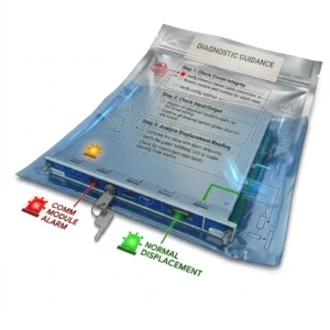
- 📊 Analyze Fault Logs: Use the PLC’s internal diagnostics to identify channel-level short circuits or open loops.
PLC Pioneer’s Expert Commentary
“From my perspective at PLC Pioneer, the shift toward ‘Smart I/O’ is changing how we troubleshoot. Modern modules compliant with IEC 61131-2 now offer granular diagnostics that can detect a broken wire before the operator even notices a process shift. While manual cross-testing remains a core skill, investing in modules with channel-level LED indicators and HART compatibility is the best way to future-proof your factory automation.” — PLC Pioneer
Frequently Asked Questions
Q: How can I tell if a lightning strike damaged my PLC or the sensors?
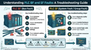
Lightning usually causes “common-mode” failures. If an entire group of 8 or 16 inputs stops responding, the surge likely bypassed the isolation barrier of the PLC module. Sensors usually fail individually unless the surge traveled through the power distribution bus.
Q: Are newer high-density input modules always better?
Not necessarily. While high-density modules save cabinet space, they often share a common ground. In electrically noisy environments, this can lead to “signal bleed” between channels. For critical safety loops, lower-density, isolated channels are often more reliable.
: What is the most overlooked factor in PLC input failures?
Inadequate grounding. Without a proper reference point, “ghost voltages” can fluctuate on analog inputs, making a perfectly good sensor appear failed. Always check your shield grounding at the PLC side only to avoid ground loops.
Solution Scenario: The “Ghost” Fault in Food Packaging
A high-speed tray sealer began missing “Product Present” signals. The maintenance team initially replaced the photoelectric sensor twice, but the issue persisted. By applying our technical insights, they discovered the PLC input filter was set to 20 ms—too slow for the 15 ms pulse generated by the fast-moving tray. Lowering the filter to 3 ms resolved the “fault” without purchasing a single new part.
For more technical insights and premium hardware solutions to optimize your control systems, visit our resource center.
Explore our full range of industrial components at: PLC Pioneer Limited