
Troubleshooting ABB UFC721BE101 3BHE021889R0101: Resolving Persistent Optical Link Failures
The ABB UFC721BE101 control board serves as a core component in high-speed DCS communication architectures and static excitation systems. This board manages deterministic optical transmission between controller racks, drive interfaces, and critical protection modules. However, field engineers frequently encounter stubborn “Optical Link Error” alarms that persist even after swapping the fiber optic cables. In these scenarios, the root cause typically points to the degradation of the onboard photoelectric conversion IC rather than the external fiber pathway itself.
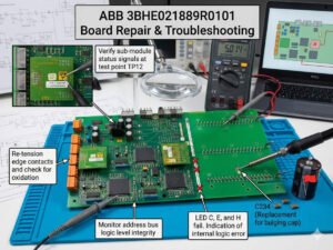
The High Cost of Intermittent Optical Communication Faults in DCS Environments
Unplanned downtime remains a major challenge in power generation, petrochemical, and heavy manufacturing sectors. According to industrial automation research, unexpected outages cost large plants thousands of dollars per minute. Intermittent optical communication faults on the UFC721BE101 board can instantly trigger sudden I/O loss, excitation trip alarms, or synchronization instability. Consequently, engineers must accurately isolate whether the failure originates from the optical transceiver module, the FPGA communication channel, or the internal power conditioning section to avoid unnecessary hardware replacement costs.
Technical Mechanism: Why Onboard Photoelectric Conversion Fails
The onboard photoelectric conversion circuit relies on an optical transmitter, an RX photodiode, a signal conditioning IC, and an FPGA interface. In ABB excitation systems, these components operate under microsecond-level timing tolerances. As a result, a degraded optical receiver might still detect the presence of light but fail to pass cyclic redundancy check (CRC) or frame synchronization validation. This technical degradation causes intermittent LINK LED flashing and persistent optical alarms that temporarily disappear after a cold restart.
Thermal Cycling and Component Degradation in Industrial Automation Control Systems
Harsh factory automation environments accelerate the aging of Vertical-Cavity Surface-Emitting Lasers (VCSEL) and photodiode components. For instance, continuous thermal cycling in unventilated control cabinets with temperatures exceeding 55°C leads to localized component attenuation. Accumulated industrial dust further reduces optical sensitivity. At PLC Pioneer, we observe that these degraded boards often appear functional under idle conditions but trigger fatal communication faults when network load spikes during peak production periods.
Monitoring Power Rail Stability in Integrated Control Systems
The integrated optical transceiver circuit depends entirely on stable +3.3V and +5V low-noise reference voltage rails to maintain signal integrity. If electrical ripple exceeds strict industrial tolerances, the photoelectric conversion IC enters an unstable operating state without experiencing total hardware failure. Engineers should utilize precise test points to maintain system health, as summarized below:
- ✅ 3.3V DC Ripple Monitoring: Maintain ripple levels below 50mVpp to prevent RX data decoding errors.
- ⚙️ TX Bias Current Verification: Verify current stability under full communication load to ensure consistent optical transmission power.
- 🔧 RX Output Waveform Analysis: Ensure a clean, sharp square wave to preserve deterministic communication timing across the backplane.
Furthermore, aging electrolytic capacitors within the power conditioning stage often introduce excessive noise. Therefore, replacing external fiber cables provides no resolution for this specific internal board issue.
Deterministic Timing Requirements vs. Standard Ethernet Signaling
Many ABB optical interfaces deploy proprietary, deterministic communication timing protocols rather than generic Ethernet signaling. Consequently, even when an optical power meter indicates normal light levels, minor timing skew between the TX and RX channels can still disrupt the network link. This strict synchronization requirement is crucial for turbine control systems and high-speed synchronization loops. For this reason, field engineers must avoid uncertified third-party optical modules that do not precisely match the original ABB hardware rise and fall time specifications.
An Oscilloscope-Based Diagnostic Sequence for Maintenance Teams
Immediately replacing an entire control board when an optical alarm surfaces is an inefficient and costly maintenance practice. Instead, technicians should adopt a systematic diagnostic sequence to isolate the fault. First, measure the external optical fiber attenuation. Second, verify the TX optical output power at the port. Third, probe the RX electrical output waveform utilizing a high-bandwidth oscilloscope. Finally, confirm the clock synchronization on the FPGA side. If the oscilloscope reveals an unstable data framing structure despite a solid RX waveform amplitude, the fault resides within the internal conversion stage.
Three Board-Level Testing Methods for Field Engineers
To pinpoint failures on the ABB UFC721BE101 3BHE021889R0101 board, implementation of the following testing methodologies is highly recommended:
- 📊 Method 1: Optical Power Measurement: Disconnect the RX fiber link, measure the TX output power with an industrial power meter, and compare the value against a known healthy channel to detect laser aging or insufficient bias voltage.
- 📊 Method 2: Electrical Signal Probing: Connect an oscilloscope to the electrical side of the optical receiver IC. A collapsed waveform, random pulse distortion, or excessive jitter indicates a failed comparator stage or FPGA interface degradation.
- 📊 Method 3: Local Optical Loopback Test: Connect a short, certified optical jumper cable directly from the TX port to the RX port on the same board. If the link alarm persists, the board-level optical circuit is definitively faulty, effectively ruling out the external field fiber network.
Implementing a local loopback remains one of the fastest isolation methods during planned plant shutdown maintenance windows.
Environmental Controls Control Component Lifespan
In petrochemical facilities and heavy steel mills, ambient environmental hazards cause more optical communication failures than inherent component defects. Conductive dust accumulation, poor cabinet airflow, and grounding potential differences create severe electrical stress. Additionally, continuous structural vibration causes micro-loosening of fiber connectors. To mitigate these risks, maintain cabinet temperatures below 45°C, mandate optical port cleaning during annual shutdowns, enforce proper fiber bending radiuses, and secure all board locking clips.
—
PLC Pioneer’s Expert Perspective
“In my years tracking industrial automation trends, I have seen hundreds of control boards discarded prematurely due to simple optical transceiver degradation. The ABB UFC721BE101 is a rugged piece of engineering, but it cannot overcome poor power quality or extreme thermal stress. Before authorizing an expensive full-board replacement, modern maintenance teams should invest twenty minutes in oscilloscope analysis. Component-level refurbishment or targeted chip replacement often yields identical uptime results at a fraction of the capital expenditure.” — PLC Pioneer
Expert Practical FAQs
Q: How do we evaluate if a degraded UFC721BE101 board is candidates for repair or requires scrap?
If you confirm stable power rails and normal optical power output, but the FPGA communication interface remains completely non-responsive during loopback testing, the internal ASIC logic may be permanently damaged. However, if the fault is isolated to distorted waveforms at the comparator or receiver IC stage, board-level component replacement is highly economical and technically viable, provided the multilayer PCB traces show no signs of delamination or overheating.
Q: What specific firmware risks occur when swapping these communication boards?
When deploying a replacement board, matching the physical part number 3BHE021889R0101 is insufficient. You must verify that the onboard flash firmware revision aligns with your existing rack controller backplane and excitation software version. Mixing mismatched firmware generations often introduces subtle timing variances that trigger intermittent synchronization alarms only when the system runs under full operational load.
Q: Can we upgrade the optical transceivers on older boards to handle longer fiber runs?
We strongly advise against modifying the transceiver specifications. The deterministic timing loops of the ABB system are precisely calibrated to the propagation delay, rise times, and fall times of the original components. Altering the transceiver hardware to increase optical launch power or distance will alter these timing characteristics, potentially causing cyclic redundancy check (CRC) errors and protocol instability across the control network.
—
Application Scenario: Excitation System Synchronization Realized
Consider a major utility plant operating a synchronous generator where the excitation control loop experienced unpredictable tripping. The maintenance team replaced the external fiber cables twice, yet the optical link error returned during peak mid-day thermal loading. By applying Method 3, the engineers performed a local loopback test which proved the error was internal. Oscilloscope probing revealed a degraded +3.3V power rail capacitor that induced noise into the optical receiver circuit. Replacing the capacitor restored complete system synchronization and prevented a multi-day generation outage.
If you require reliable replacement parts, certified firmware validation, or expert technical documentation to maintain your critical DCS and excitation infrastructure, please connect with our specialized support engineering team.
Visit our official resource center for advanced technical guides and industrial hardware support: PLC Pioneer Limited