Maximizing the Operational Life of PLC Relay Outputs in High-Frequency Industrial Applications
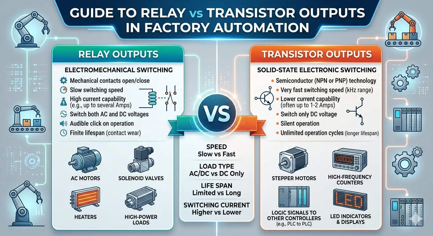
Relay-output PLCs remain a cornerstone of industrial automation due to their robust electrical isolation and ability to drive diverse AC/DC loads. These modules excel at switching inductive components like contactors and solenoid valves. However, mechanical wear often limits their performance in high-speed environments. Understanding these constraints is vital for maintaining system uptime in bottling plants and discrete manufacturing sectors.
The Critical Gap Between Mechanical and Electrical Life
Engineers often mistake a relay’s mechanical life for its actual operational lifespan. While a relay might cycle 20 million times without a load, its electrical life drops significantly under stress. For resistive loads, you may see 500,000 cycles, but inductive loads often reduce this to 100,000. At PLC Pioneer, we emphasize that continuous 2 Hz switching can exhaust a relay in less than 24 hours.
How Switching Frequency Dictates System Stability
High-frequency operations accelerate contact erosion and heat buildup within the PLC housing. Most manufacturers recommend a frequency below 0.5 Hz to ensure long-term reliability. Exceeding these limits often results in “welded” contacts or intermittent control failures. Therefore, high-speed pulse applications should utilize transistor outputs instead of mechanical relays to avoid unplanned maintenance cycles.
Mitigating Arc Damage Through Surge Suppression
Inductive loads generate high back-EMF, which creates severe arcing across relay contacts during disconnection. Implementing proper suppression is not optional for professional factory automation. We recommend using flyback diodes for DC circuits and RC snubbers for AC loads. These components effectively extend contact life by up to five times by absorbing destructive electrical energy.
Field Strategies for Hardware Protection and Maintenance
In high-cycle sorting systems, driving heavy loads directly from the PLC is a risky practice. Instead, use the PLC to trigger an external interposing relay or a Solid State Relay (SSR). This strategy ensures that cheap, external components bear the wear rather than the expensive internal PLC circuitry. Additionally, using ferrules and verified torque settings prevents localized heating in high-vibration environments like mining.
Strategic Procurement: When to Upgrade Your Output Architecture
If your maintenance logs show relay failures every few months, it is time to reconsider your hardware selection. Upgrading to transistor outputs or SSRs is essential if switching exceeds one cycle per second. When sourcing replacements, always verify compliance with the IEC 61131-2 standard. Moreover, ensure that new modules can handle the specific inrush currents of your existing field devices.
Best Practices for Industrial Relay Integration
- ✅ External Interposing: Use external relays for high-load or high-frequency tasks to protect the PLC.
- ⚙️ Load-Side Suppression: Install surge protectors directly at the load to minimize EMI interference.
- 🔧 Thermal Management: Maintain proper spacing between PLC modules to dissipate heat from active relays.
- 📊 Cycle Monitoring: Use PLC software counters to track relay operations and schedule predictive replacements.
PLC Pioneer’s Expert Commentary
“In my years of field auditing, I have found that ‘sticky’ outputs are rarely a manufacturer defect. Instead, they usually stem from improper load matching. In 2026, as we move toward smarter factory automation, integrating hybrid output strategies—using relays for isolation and transistors for speed—is the most cost-effective way to ensure 99.9% reliability.” — PLC Pioneer
Frequently Asked Questions
Q: Why did my PLC relay fail even though the current was within the rated limit?
Current is only half the story; inrush current and back-EMF are the real relay killers. Inductive loads like motors can draw 10 times their nominal current at startup, causing micro-welds on the contacts that eventually lead to permanent failure.
Q: Can I mix AC and DC loads on the same relay output module?
Technically, yes, if the module provides isolated commons for different points. However, mixing voltages on a single common header increases the risk of short circuits during maintenance. We suggest dedicating specific modules to specific voltage types for better safety.
Q: Is there a way to ‘soften’ the switching to save the relay?
For mechanical relays, the physical movement is fixed. However, adding an RC circuit helps suppress the arc. If you need true soft-switching or PWM, you must transition to a transistor-based system or a specialized motor starter.
Solution Scenario: The High-Speed Conveyor Upgrade
A logistics facility experienced PLC failures every three months on their high-speed diverter line. By replacing the direct PLC-to-solenoid connection with an SSR interposing layer and adding MOV surge suppressors, the facility extended its maintenance interval to over two years. This simple change saved thousands in hardware costs and prevented critical downtime during peak seasons.
For more technical insights on optimizing your industrial hardware or to source high-quality automation components, please visit our resource center.
Explore our full range of industrial solutions at: PLC Pioneer Limited