Mastering PLC Performance: Resolving the “Cycle Time Exceeded” Watchdog Fault
In the world of industrial automation, precision timing defines the boundary between seamless production and catastrophic failure. A “Cycle Time Exceeded” alarm occurs when the PLC program scan time surpasses its predefined watchdog limit. Consequently, the controller fails to complete its logic execution within the expected timeframe. This issue threatens deterministic control, particularly in high-stakes sectors like petrochemicals and pharmaceutical processing.
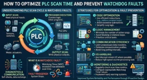
Understanding the Mechanics of PLC Scan Cycle Time
The scan cycle represents the total duration required for the PLC to read inputs, execute user logic, and update outputs. If this cycle takes too long, outputs may respond late. As a result, motion systems may misalign or batching processes may suffer from critical timing errors. Inefficient code, such as excessive nested loops or massive data arrays, often drives these delays. Moreover, blocking instructions during communication can stall the processor significantly.
Strategic Watchdog Timer Configuration and Risks
The watchdog timer serves as a safety net for the control system. However, improper configuration creates new risks. Setting the limit too tight leads to frequent nuisance trips during minor CPU spikes. Conversely, a setting that is too loose masks underlying performance bottlenecks. Ideally, the watchdog should reflect the physical safety requirements of the process, such as burner management or high-speed dosing loops.
Analyzing CPU Load and Task Prioritization
Modern control systems, including modular DCS architectures, utilize multitasking with varying priority levels. When CPU utilization exceeds 80%, the risk of cycle overruns increases dramatically. Poorly prioritized tasks can allow low-priority data logging to delay time-critical motion control. I once observed a packaging line where excessive HMI polling flooded the CPU, triggering intermittent faults during peak production speeds.
Optimization Techniques for Industrial Control Systems
Engineers should optimize program structures before considering expensive hardware upgrades. First, replace inefficient loops with indexed logic to streamline execution. Second, utilize interrupt tasks for operations requiring millisecond precision. Finally, offload non-essential functions like heavy data logging to edge devices or SCADA systems. These steps often restore stability without requiring new PLC modules.
Best Practices for Communication and Networking
Heavy industrial networking over Ethernet/IP or Modbus TCP can introduce significant jitter. Therefore, engineers should separate control networks from data-heavy business networks. Using asynchronous communication blocks instead of blocking calls prevents the CPU from waiting on external devices. Furthermore, avoid polling too many field devices within a single scan cycle to maintain predictable performance.
Commissioning Strategies and Trend Monitoring
Static testing during a Factory Acceptance Test (FAT) rarely reveals timing issues. Instead, engineers must log scan time trends under full production loads. Simulate worst-case scenarios, including communication bursts and simultaneous alarm events. This proactive monitoring ensures the system remains resilient during real-world operation. Reliable systems require at least 30% to 40% performance headroom for long-term stability.
Technical Implementation Summary
- ✅ Code Efficiency: Simplify logic to reduce the average execution time per scan.
- ⚙️ Task Management: Assign high priority to safety and motion tasks over background comms.
- 🔧 Network Segmentation: Isolate I/O traffic from SCADA and HMI data streams.
- 📊 Stress Testing: Validate the watchdog limit during maximum I/O and alarm activity.
Expert Commentary by PLC Pioneer
“I often see engineers treat the ‘Cycle Time Exceeded’ fault as a hardware limitation, but it is usually a symptom of ‘software bloat.’ As we integrate more Industry 4.0 features like real-time analytics directly into the PLC, the CPU load increases. My advice is to always design with a ‘lean logic’ mindset. According to industry standards like IEC 61131-3, maintaining deterministic execution is more valuable than cramming every function into a single controller.” — PLC Pioneer
Frequently Asked Questions (FAQ)
Q: How do I determine if my code or my hardware is the bottleneck?
Monitor the ‘Maximum Scan Time’ register in your PLC diagnostics. If the time spikes only during specific events (like a shift change or data export), the issue is likely communication-related. If the scan time is consistently high, your logic requires optimization or a faster CPU.
Q: Can firmware updates impact the PLC cycle time?
Yes. New firmware versions often introduce enhanced security features or updated instruction sets that may slightly increase CPU overhead. Always perform a timing verification after any firmware migration to ensure your watchdog settings remain valid.
Q: What is the risk of simply increasing the watchdog timer limit?
Increasing the limit stops the alarm but doesn’t fix the latency. In high-speed manufacturing, a delayed output can cause mechanical collisions or inconsistent product quality. Only increase the limit if the physical process can safely tolerate the resulting delay.
Application Scenario: High-Speed Beverage Bottling
In a bottling facility, a PLC manages synchronization between the conveyor and the filling valves. When the scan time fluctuated due to heavy SQL logging, the valves opened 15ms late, leading to significant product waste. By moving the logging tasks to a separate periodic task with lower priority, the engineer stabilized the filling cycle and eliminated the watchdog faults.
To optimize your system performance and browse the latest in high-speed industrial controllers, visit our resource center for expert support.
Explore high-performance automation solutions: PLC Pioneer Limited