Why Single-Point Grounding for IS200TRTDH1CCC RTD Wiring Safeguards Control Systems
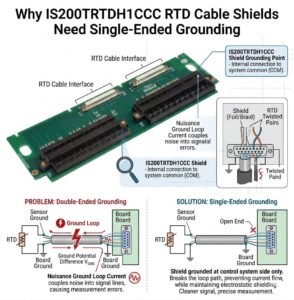
In GE Mark VI and Mark VIe control systems, the IS200TRTDH1CCC RTD terminal board plays a critical role. It acquires low-level resistance signals from Resistance Temperature Detectors (RTDs) to safeguard high-value machinery. Because RTD circuits operate on milliohm-level variations, electromagnetic interference (EMI) can easily corrupt the data. Engineers frequently ask why they must ground the cable shield at only one end. The answer involves eliminating ground loops while maintaining robust signal protection on the factory floor.
Understanding RTD Signal Sensitivity in Modern Industrial Automation
Unlike high-voltage discrete control loops, RTD sensors measure minute electrical resistance changes to calculate temperature. For instance, a standard Pt100 sensor shifts by merely 0.385 ohms for every degree Celsius change. Consequently, even minor induced noise from nearby power lines can compromise measurement accuracy. If you ground the cable shield at the terminal board only, the shield becomes an effective electrostatic barrier. This barrier successfully diverts ambient electrical noise away from the core signal conductors.
Eliminating Ground Loops across Distributed Control Networks
The primary reason for single-ended grounding centers on preventing devastating ground loops. Large industrial automation facilities often feature distinct ground grids that possess slight differences in electrical potential. If field technicians connect the shield at both the RTD head and the IS200TRTDH1CCC board, they create a closed conductive circuit. This loop inadvertently carries stray currents from variable frequency drives (VFDs) or heavy machinery. Therefore, single-point grounding isolates the shield and preserves control system stability.
Aligning Hardware Integration with GE Mark VIe Architecture
The internal circuitry of the IS200TRTDH1CCC features a dedicated reference ground designed for noise attenuation. Grounding the shield exclusively at the terminal board side optimizes common-mode rejection ratios. Moreover, this practice complies fully with standard **IEEE 1050** guidelines for instrumentation grounding in power plants. If you ground both ends, you alter the input impedance characteristics of the board. As a result, the built-in noise filters cannot perform at their engineered capacity.
Field-Proven Separation Strategies for Factory Automation Cables
Improper cable routing remains a leading cause of signal degradation in heavy industry. Field engineers often mistakenly run sensitive instrumentation cables alongside high-current motor feeders or excitation lines. To maximize signal integrity, maintain a physical separation of at least 30 centimeters in open trays. If the cables must intersect, ensure they cross at a perfect 90-degree angle to minimize mutual inductance. These simple physical layout adjustments prevent significant troubleshooting hours during commissioning.
Proper Termination Practices at the Terminal Board Block
Executing clean terminations is vital for long-term reliability in thermal monitoring applications. Technicians should connect the drained shield wire firmly to the designated chassis ground terminal on the IS200TRTDH1CCC. Conversely, they must cut back and fully insulate the shield at the field instrument enclosure. Many commissioning delays occur because electrical contractors bond the shield to the RTD housing out of habit. This mistake creates an accidental ground path that immediately degrades signal accuracy.
Diagnostic Procedures for Mitigating Temperature Signal Drift
When control systems exhibit unexplained temperature fluctuations, structured diagnostic steps can quickly isolate the root cause. First, measure the AC voltage between the disconnected field shield and the local ground structure. Next, inspect intermediate junction boxes for moisture ingress or accidental metal-to-chassis contact. In my field experience at PLC Pioneer, a breakdown in cable jacket insulation often creates intermittent grounding points. These hidden faults mimic faulty sensor behavior and complicate routine maintenance.
—
Technical Checklist & Grounding Best Practices
- ✅ Verify Single Isolation: Confirm the field-side shield remains fully floating and insulated inside the sensor head.
- ⚙️ Enforce Signal Segregation: Never route low-level RTD lines within the same conduit as AC power distribution wiring.
- 🔧 Check Terminal Tightness: Periodically inspect the IS200TRTDH1CCC connections to prevent high-resistance contact points.
- 📊 Document Ground Changes: Record all modified shield terminations in the master plant loop diagrams immediately.
—
PLC Pioneer’s Industry Perspective
“Many plant managers treat shield grounding as a minor detail rather than a core engineering protocol. However, in modern combined-cycle power plants or complex petrochemical facilities, minor signal noise can cause catastrophic turbine trips. As control system designs evolve in 2026, the reliance on high-density I/O modules makes proper shielding infrastructure more critical than ever. Skipping single-point grounding rules to save installation time always results in long-term operational vulnerability.” — PLC Pioneer
Field Experience & Troubleshooting Q&A
Q: What happens if a field technician accidentally grounds both ends of an RTD shield?
When you ground both ends, the potential difference between the control room and the field drives an active current through the shield. This current creates an electromagnetic field that induces noise directly into the signal wires, causing temperature readings to drift randomly whenever nearby heavy motors start up.
Q: How can we identify a hidden ground loop without shutting down the process?
You can use a high-resolution AC clamp meter capable of measuring milliamps to test the shield wire. Any measurable current flowing through an instrumentation shield confirms the presence of a ground loop, indicating an accidental secondary grounding point somewhere along the cable run.
Q: Does the length of the cable run affect single-point grounding efficiency?
Yes, longer cable runs increase the cumulative capacitance of the line, which makes the circuit more vulnerable to high-frequency noise. For runs exceeding 100 meters, using individually shielded twisted-pair cables alongside single-point grounding is mandatory to prevent severe signal attenuation.
—
Application Scenario: Gas Turbine Bearing Protection
Consider a large power generation facility utilizing a GE Mark VIe system to monitor critical bearing temperatures on a gas turbine. During initial operation, the bearing temperature readings fluctuated by 5 degrees Celsius every time the auxiliary pumps engaged. An inspection revealed that the installation crew bonded the RTD shields to both the turbine frame and the IS200TRTDH1CCC board. After floating the shield at the turbine side, the signal stabilized instantly, preventing an imminent nuisance trip of a multi-million dollar asset.
If you need to optimize your industrial control system layout or require certified turbine control components to replace aging hardware, explore our extensive inventory of genuine automation modules.
Discover comprehensive technical resources and premium hardware solutions at our main site: PLC Pioneer Limited