Troubleshooting Bently Nevada 330730-040-00-00 Extension Cable Faults on 3500/42M Monitors
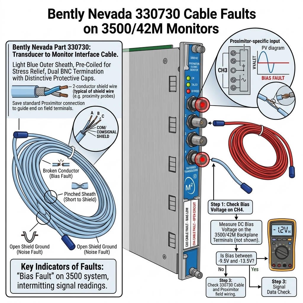
In machinery protection systems, proximity probes demand seamless physical infrastructure to maintain measurement accuracy. The Bently Nevada 330730-040-00-00 extension cable acts as a vital calibration link within the 3300 XL 8mm eddy current sensor system. However, physical splices or damaged insulation on this cable severely disrupt the system impedance. When paired with a 3500/42M Proximitor Seismic Monitor, this damage triggers specific, predictable drift in gap voltage.
Understanding Eddy Current Gap Voltage Shift and Signal Degradation
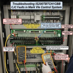
A standard 3300 XL proximity probe system delivers a precise DC bias voltage to reflect the physical gap. Under normal operating conditions, a wider gap produces -17V to -24V, while a closer gap reads -8V to -12V. However, cable splices introduce contact resistance and localized oxidation. This attenuation forces the Proximitor to drop its output signal, causing the bias voltage to drift toward a more negative state. Consequently, the 3500/42M monitor often flags a “Gap Voltage Low” or a “Not OK” hardware fault status.
How Cable Insulation Failures Alter Total System Capacitance
The entire transducer loop requires strict calibration based on a fixed combined electrical length. According to the API 670 standard for machinery protection, any modification to the cable core alters loop capacitance. On critical rotating assets like turbocompressors running above 3000 RPM, splices create immediate impedance mismatches. Therefore, moisture ingress or degradation within an unsealed joint manifests as phantom 1X vibration spikes. Plant engineers frequently misdiagnose these phantom spikes as bearing wear when the true root cause remains a compromised cable.
The Mechanical Mechanics of Shielding Failures and Ground Loops
Industrial environments expose extension cables to harsh physical stresses, leading to torn outer jackets. When a damaged cable shield makes direct physical contact with the machine frame or cable tray, it establishes a localized ground loop. This ground loop allows external electromagnetic interference (EMI) to infiltrate the low-voltage sensor circuit. As a result, the 3500/42M seismic monitor registers high channel noise, which quickly triggers a “Channel Not OK” status rather than a standard vibration limit alert.
Analyzing Rare Scenarios: When Does Bias Voltage Drift High?
While negative voltage drops dominate field failures, specific short circuits can cause a less negative, or “high,” gap voltage. For example, a severe insulation crush might pinch the center conductor directly against the outer shield. This direct short reduces the path resistance, pulling the bias voltage from -10V up toward -3V. However, my diagnostic experience indicates that these short circuits are highly unstable. The component will typically deteriorate into a hard “Not OK” fault within minutes rather than operating with a stable high bias.
How Liquid Ingress Creates Random Intermittent Fault Profiles
In humid petrochemical facilities or offshore platforms, condensation regularly pools inside unsealed junctions. This moisture bridges the internal conductors, creating an unpredictable, fluctuating leak path. Operators watching the 3500 rack will observe the gap voltage swinging erratically between -8V and -14V. This unstable performance complicates real-time diagnostics. Ultimately, the system requires complete removal of the spliced segment to restore stable signal transmission across the loop.
Enforcing API 670 Standards: The Case Against Cable Splices
Engineering teams often splice extension cables as a quick fix during forced outages to save time. However, field data from large-scale power generation plants shows that spliced cables account for over forty percent of unexpected sensor failures. Splicing permanently alters the factory-calibrated impedance. Therefore, to maintain loop integrity on critical turbomachinery, plant managers must completely ban the use of permanent inline splices. Replacing the entire run with a single continuous cable ensures maximum reliability.
—
Proximity Loop Maintenance Best Practices & Field Diagnostics
- ✅ Verify Loop Integrity: Always replace spliced cables on API 670 loops immediately during the next planned maintenance window.
- ⚙️ Isolate Sensor Lines: Run proximity probe cables through dedicated, grounded conduits away from high-voltage motor supply lines.
- 🔧 Protect Frontend Hardware: Always disconnect the Proximitor sensor module physically before running insulation tests with a 500V or 1000V megohmmeter.
- 📊 Test Dynamic Resistance: Flex the extension cable gently near the connections while measuring resistance to catch intermittent, vibration-induced open circuits.
—
PLC Pioneer’s Expert Commentary
“Throughout my years managing critical machine protection systems, I have watched instrument technicians replace perfectly good proximity probes because they misread a negative gap voltage shift. It is vital to remember that an engineered cable loop is a single unified component. In modern factory automation and DCS environments, false trips cost thousands of dollars per hour. Treating the extension cable as a secondary accessory is a major mistake; it is just as critical as the monitor itself.” — PLC Pioneer
Industrial Automation Field FAQs
Q: Why does the 3500/42M show an asset vibration change when I wiggle a spliced cable?
The physical movement alters the contact resistance across the individual spliced wire strands in real time. This rapid resistance change mimics an active AC dynamic signal, which the 3500/42M interprets as actual physical shaft vibration.
Q: What is the most efficient way to isolate a fault between a probe and an extension cable?
We recommend utilizing the three-step substitution method. Measure the voltage directly at the Proximitor terminal, then isolate the cable by connecting a known good test cable directly to the probe to see if the voltage stabilizes.
Q: Can specialized heat-shrink kits make an extension cable splice safe for long-term use?
No, heat-shrink kits protect against moisture but cannot restore the uniform electrical capacitance of the original coaxial shielding. The system will continue to suffer from impedance discontinuities that affect high-frequency calibration.
—
Real-World Application Scenario: Turbocompressor Diagnostic Recovery
An industrial gas plant experienced recurring “Channel Not OK” faults on a critical compressor monitored by a Bently Nevada 3500/42M system. The gap voltage on the X-axis radial vibration channel kept drifting from a normal -11V to -21V, causing intermittent system bypasses. While local technicians initially blamed a loose probe bracket, an inspection revealed an unrecorded, spliced 330730 extension cable hidden inside a junction box. The splice had oxidized due to moisture. Replacing the compromised wire with a continuous cable completely resolved the voltage drift and restored the machine protection loop.
If you need to replace damaged instrumentation lines or want to upgrade your control systems with premium hardware components, explore our comprehensive inventory of industrial solutions.
Visit our official resource center for technical guides and hardware support: PLC Pioneer Limited