
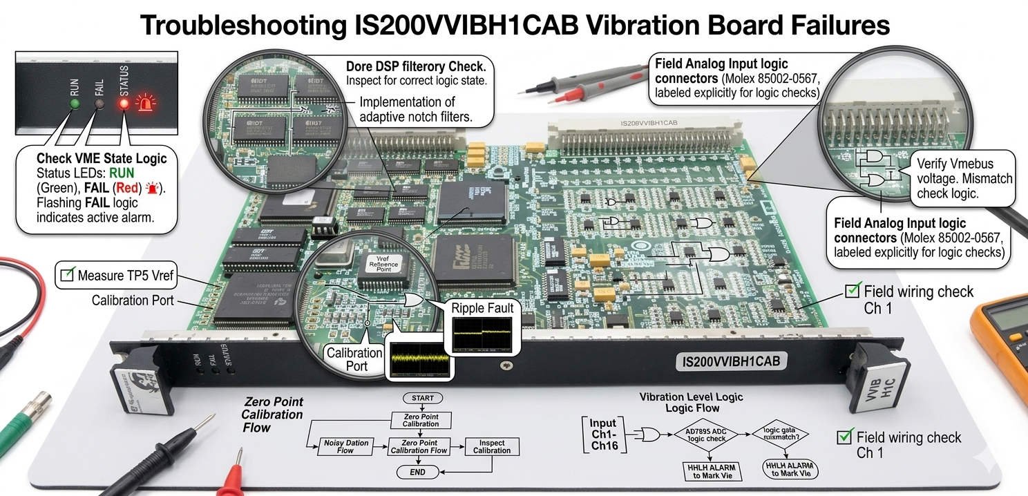
Troubleshooting Probe Power Failure on the GE Mark VIe IS200VVIBH1CAB Vibration Board
The GE EX2100 and Mark VIe vibration interface board, specifically the IS200VVIBH1CAB model, plays a critical role in turbine protection. This specialized hardware supplies a stable -24VDC excitation voltage to eddy current proximity probes. Furthermore, it conditions complex vibration signals before routing them to the primary turbine control systems. However, unstable sensor power often triggers false vibration alarms, disrupts shaft position feedback, or causes catastrophic turbine trips.
Understanding the Critical Link Between Resistor Degradation and Signal Integrity
The onboard current-limiting resistor within the IS200VVIBH1CAB power supply block actively protects the -24VDC circuit against overcurrent conditions. Unfortunately, long-term exposure to high ambient temperatures within industrial automation panels drives severe resistance drift. Consequently, the probe excitation voltage may drop from a stable -24VDC down to -18VDC. This voltage reduction causes highly unstable shaft vibration readings during critical machine startup phases.
Why Dynamic Load Testing Beats No-Load Multimeter Inspections
Field technicians frequently make the mistake of measuring probe voltage only when sensors remain disconnected. A degraded current-limiting resistor can easily mask its true condition by showing perfect nominal voltage under no-load states. However, the voltage collapses immediately once you connect the sensor load. Therefore, our engineering team recommends implementing dynamic voltage-drop tests alongside offline static resistance checks to guarantee reliable circuit analysis.
Mitigating Severe Thermal Stress and Environmental Hazards in Turbine Cabinets
Control cabinets housing EX2100 and Mark VIe systems near turbine decks regularly face hostile working conditions. These harsh factors include sustained high temperatures, conductive oil mist, and continuous structural vibration. As a result, these elements accelerate solder joint fatigue and cause rapid oxidation on power resistors. Studies indicate that control system circuit boards operating above 55°C face double the component failure rates.
—
Step-by-Step Guide: Testing the Onboard Current-Limiting Resistor
When your turbine control system logs a PROX FAIL or VIBRATION INPUT BAD alarm, follow this precise troubleshooting procedure:
- Isolate the Board: Remove all external field wiring from the target vibration probe channels. Then, safely power down the Mark VIe rack and extract the IS200VVIBH1CAB module from its backplane slot.
- Locate the Power Section: Trace the PCB layout near the DC/DC conversion stage and output terminals. Visually inspect the board surface for darkened areas, cracked cement resistors, or brittle flux residues.
- Measure Offline Resistance: Switch your digital multimeter to resistance mode. Measure the component and compare your readings directly against a known-good adjacent channel to isolate thermal drift.
- Execute a Dynamic Load Test: Reinstall the module, apply system power, and connect a simulated sensor load. Measure the exact voltage drop across the resistor to verify circuit stability under load.
—
Implementation Checklist & Technical Insights
- ✅ Reject Jumper Bypasses: Never use a temporary jumper wire to bypass a failed current-limiting resistor on critical DCS control boards. Bypassing permanently destroys short-circuit protection and risks total DC/DC converter failure.
- ⚙️ Verify Sensor Matching: Always check probe manufacturer guidelines and extension cable lengths before hardware replacement. Mismatched eddy current probes draw excessive current and can easily overload the excitation circuitry.
- 🔧 Inspect Secondary Components: Look closely at surrounding protection zener diodes and output transistors during repairs. A burned resistor usually points to a secondary short-circuit condition in adjacent components.
—
PLC Pioneer’s Expert Commentary
“In my long-term observation of factory automation trends, industrial plants frequently misdiagnose board-level power issues as simple field instrument faults. On the GE Mark VIe platform, power supply degradation on the IS200VVIBH1CAB is a classic hidden culprit behind intermittent machine trips. In 2026, maintaining absolute signal integrity is non-negotiable for predictive maintenance. Therefore, I strongly advise operators to replace aging boards rather than relying on unreliable component-level fixes for critical turbine lines.” — PLC Pioneer
Frequently Asked Questions
Q: What causes a specific vibration channel to fail while adjacent channels on the same board function perfectly?
This localized failure occurs because the IS200VVIBH1CAB utilizes independent current-limiting resistors and filtering circuits for its individual channels. A localized short circuit in field wiring or a localized component failure on the board will isolate the damage to that specific channel without dropping total board power.
Q: Can environmental contamination trigger false alarms without causing permanent component damage?
Yes, conductive oil mist combined with ambient dust creates high-resistance leakage paths across sensitive PCB traces. This contamination alters the bias voltage of the proximity probe circuit. Cleaning the board thoroughly with industrial electronic cleaner often restores correct readings before permanent trace burning occurs.
Q: How do firmware upgrades impact the replacement of older board revisions?
While the physical form factor of the IS200VVIBH1CAB remains identical across revisions, certain control blocks within the Mark VIe DCS require specific I/O configuration updates. Always cross-check your existing system configuration files against the new board revision suffix to prevent configuration mismatch errors during startup.
—
Application Scenario: Heavy Gas Turbine Retrofit
During a recent maintenance shutdown at a combined-cycle power plant, a gas turbine experienced repetitive, unexplained vibration trips during synchronization. The plant operators initially replaced two proximity probes, but the system fault persisted. By analyzing the system trends, our engineers found that the -24VDC excitation voltage collapsed by 15% under load due to a degraded current-limiting resistor on the IS200VVIBH1CAB card. Replacing the faulty card stabilized the sensor supply, eliminated the phantom trips, and saved the plant an estimated $50,000 in daily downtime.
If you need to source authentic replacement boards or require high-reliability hardware to secure your turbine monitoring systems, explore our extensive inventory of genuine control parts.
Visit our official resource center for technical guides and hardware support: PLC Pioneer Limited