Understanding PLC Sink and Source Wiring: Preventing Costly Polarity Errors in Industrial Automation
In the world of industrial automation, wiring polarity is a fundamental yet frequently misunderstood concept. Mistaking “Source” for “Sink” in a PLC digital input circuit does more than just cause signal failure. It often leads to damaged input channels or field devices. For industries like oil and gas or food processing, these minor wiring errors translate into significant downtime and hidden maintenance costs. Proper understanding of current flow ensures signal integrity and long-term hardware reliability.

Technical Deep Dive into Sink and Source Compatibility
PLC input modules are specifically engineered as either Sink or Source types. These must correspond correctly with the output types of field devices, such as NPN or PNP sensors. If you pair a Sink PLC with a PNP sensor, the circuit will fail to conduct. This results in a “false fault” that halts production. While some high-end modules handle errors gracefully, budget-friendly hardware may suffer from reversed current paths. This can permanently burn out internal optocouplers or current-limiting resistors.
The Critical Role of Voltage Tolerance and Standards
Most industrial control systems adhere to the 24VDC standard defined by IEC 61131-2. Modern modules typically offer a voltage tolerance of ±10% to 20%. However, this flexibility has limits. When wiring is reversed, the voltage may apply directly to internal protection diodes. This causes rapid overheating. In my experience at PLC Pioneer, I have observed that devices are much more likely to fail when operating near the upper voltage limit, such as 28VDC, during a polarity error.
Evaluating Internal Protection and Equipment Longevity
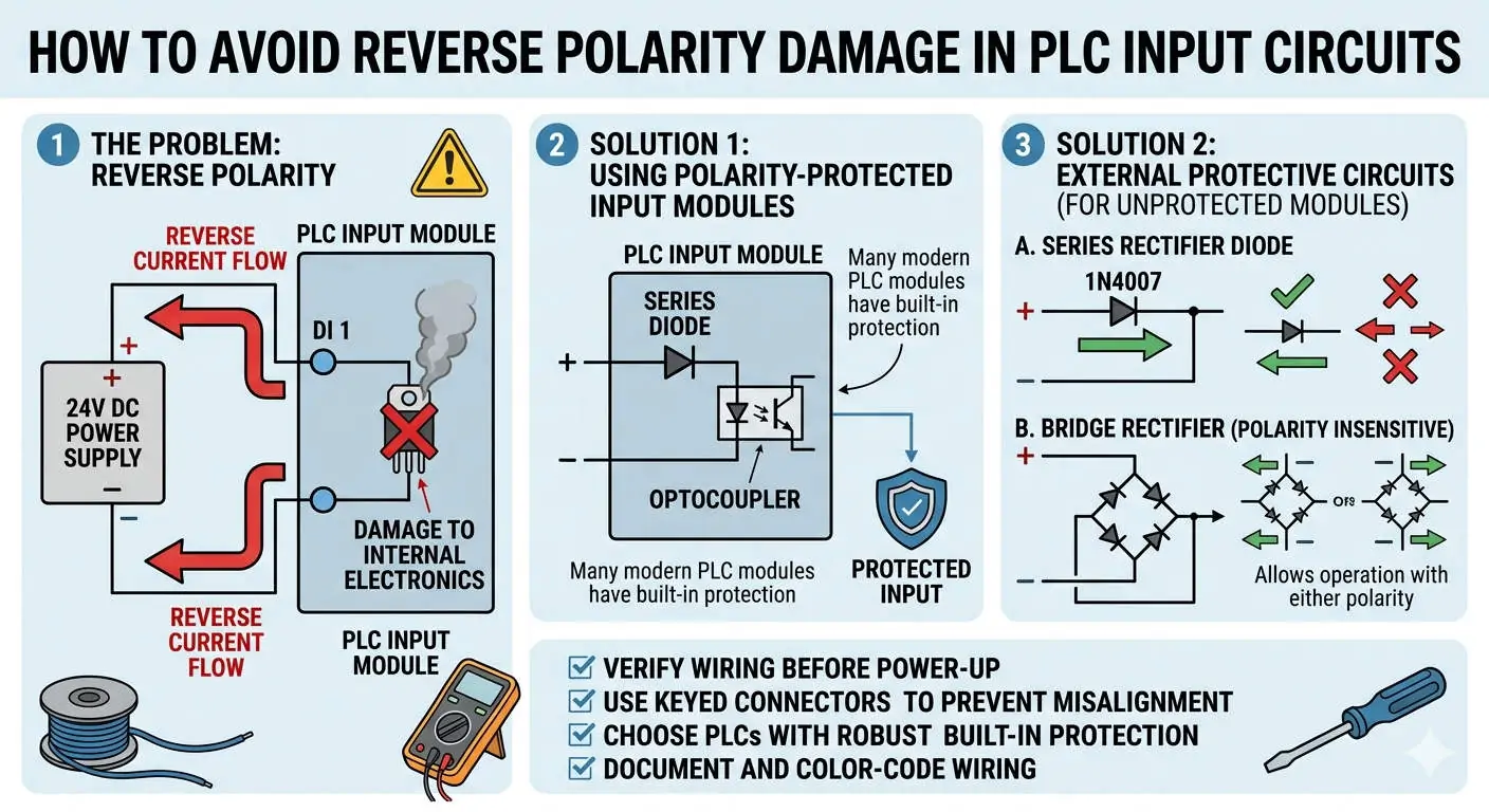
Quality PLC modules feature optoisolation and reverse polarity protection diodes. This design ensures that if a technician reverses the wires, the module simply remains inactive rather than self-destructing. In contrast, older or economy-grade models often lack these safeguards. Therefore, I strongly recommend prioritizing modules that meet international industrial standards for short-circuit and reverse-connection protection during the procurement phase.
Field Installation and Maintenance Best Practices
When technical drawings are missing or labels are unreadable, you can use a multimeter for quick identification. A PNP (Source) sensor output measures against +24V, while an NPN (Sink) sensor measures against 0V. This simple check is one of the most effective tools for field commissioning. Moreover, in environments with high electromagnetic interference, always use shielded cables. Proper grounding prevents ghost signals that technicians might mistake for wiring faults.
Proactive Measures for Legacy and Unprotected Systems
If your facility relies on legacy systems or modules without built-in protection, consider external remedies. Adding a series current-limiting resistor (typically 1kΩ to 4.7kΩ) can provide a safety buffer. Alternatively, using intermediate relays to isolate the PLC from the field sensors is a cost-effective way to prevent module burnout. As PLC Pioneer always suggests, an extra layer of hardware isolation is much cheaper than replacing a high-density input card.
Technical Essentials & Field Checklist
- ✅ Verify Sensor Logic: Always match NPN sensors with Sink inputs and PNP sensors with Source inputs.
- ⚙️ Check Polarity Protection: Confirm if your PLC hardware includes “Reverse Polarity Protection” (RPP) before installation.
- 🔧 Standardize Systems: Aim to use one standard (e.g., PNP/Source) across the entire plant to simplify future maintenance.
- 📊 Voltage Monitoring: Ensure power supplies do not exceed 24VDC ±15% to protect sensitive internal diodes.
PLC Pioneer’s Expert Commentary
“After 15 years in the field, I’ve learned that while a reversed wire doesn’t always result in smoke, it is never worth the gamble. The real danger isn’t just the hardware cost, but the hours of lost production during troubleshooting. In 2026, as systems become more integrated, standardized wiring and clear labeling are no longer optional—they are the backbone of a resilient automation strategy.” — PLC Pioneer
Frequently Asked Questions (FAQ)
Q: Does reversing the Sink/Source wiring always destroy the PLC port?
Not always. High-quality modules with optoisolation usually survive but will not function. However, economy models or older hardware often suffer immediate component failure. Always assume the risk is high and verify connections before powering up.
Q: Why is there a regional difference between NPN and PNP usage?
Historically, Asian markets favored NPN (Sink) systems due to cost and availability, while European and American manufacturers shifted toward PNP (Source) because it is generally considered safer in short-to-ground fault scenarios. Modern systems are increasingly flexible, but consistency within a single project is key.
Q: What is the fastest way to fix a mismatch between a sensor and a PLC?
The most reliable “quick fix” is using a small signal interface relay. It allows you to convert an NPN signal to a PNP signal (or vice versa) without replacing the expensive PLC input card or the field sensor.
Application Scenario: Chemical Dosing Control
In a recent chemical plant upgrade, we encountered a mix of legacy NPN sensors and new Source-input PLC modules. Rather than risking a direct connection, we implemented intermediate terminal blocks with built-in isolation. This not only protected the new DCS-linked PLC but also made future sensor replacements much easier for the maintenance team. Standardizing your wiring logic today prevents the “emergency patches” of tomorrow.
For high-quality automation components and expert technical support for your next project, explore our extensive catalog of PLC and DCS solutions.
Visit our official resource center for more technical insights: PLC Pioneer Limited