Relay vs. Transistor PLC Outputs: Selecting the Right Control Strategy for Industrial Reliability
Choosing between relay and transistor PLC outputs directly determines the long-term success of an automated system. In high-stakes environments like chemical processing and pharmaceutical manufacturing, an incorrect choice leads to premature hardware failure. Engineers must balance switching speed, load types, and mechanical lifespan to ensure maximum uptime. According to industry reports on factory maintenance, over 30% of PLC-related downtime stems from mismatched output modules and field actuators.
Switching Speed and High-Precision Response Times
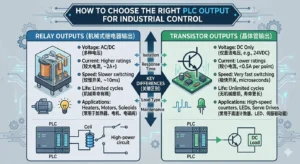
Relay outputs generally operate within a 5–15 ms window due to physical contact movement. In contrast, transistor outputs utilize solid-state electronics to switch in microseconds. This speed difference is critical for high-speed labeling machines and motion control. If you use relays for pulse-width modulation (PWM) or stepper motor signals, you will encounter missed pulses. For high-frequency applications, transistors are the only viable solution to maintain synchronization.
Load Compatibility and Voltage Flexibility
Relay outputs act as “dry contacts,” allowing them to switch both AC and DC loads up to 2A. Transistor outputs are limited to DC loads, typically at 24VDC with lower current ratings around 0.5A. While relays simplify wiring for mixed-voltage systems, they require more space. Transistors offer a compact footprint but often need interposing relays to drive high-power AC motors or large solenoids. Modern control systems frequently utilize a hybrid approach to optimize both flexibility and speed.
Maximizing Electrical Lifespan and Reducing Maintenance
Mechanical wear is the primary enemy of relay-based systems. A standard relay might last for 100,000 to 1,000,000 cycles before the contacts weld or carbonize. Transistors have no moving parts and theoretically offer an infinite lifespan if operated within thermal limits. In sorting conveyors where outputs trigger thousands of times per shift, relay failure is inevitable within months. Transitioning to solid-state logic reduces unplanned maintenance interventions and lowers the total cost of ownership (TCO).
Critical Installation Practices for Inductive Loads
Inductive loads like contactors and solenoid coils generate significant back-EMF when de-energized. Transistor outputs are highly sensitive to these voltage spikes and can fail instantly without protection. Engineers should always implement the following best practices:
- ✅ Flyback Diodes: Install across DC coils to suppressed inductive kicks.
- ✅ RC Snubbers: Use these for AC loads on relay outputs to prevent contact arcing.
- ✅ Current Derating: Avoid running all channels at maximum rated current simultaneously to prevent heat buildup.
- ✅ Vibration Dampening: Use spring-clamp terminals in high-vibration zones to prevent relay contact bounce.
PLC Pioneer’s Perspective on Future Automation Trends
At PLC Pioneer, we observe a significant shift toward “Smart Output” modules. While the relay vs. transistor debate remains fundamental, integrated diagnostics are becoming the new standard. Modern I/O modules now provide real-time feedback on short circuits and wire breaks. I recommend that engineers prioritize transistor outputs for all 24VDC logic. Reserve relays only for high-current AC switching where physical isolation is a safety requirement. This strategy aligns with the digital transformation goals of Industry 4.0.
Industrial Application Scenarios
- Scenario A (Packaging): High-speed bottle capping requires transistor outputs for precise torque control and sub-millisecond timing.
- Scenario B (Water Treatment): Large pump stations utilize relay outputs to interface directly with 230VAC motor starters, simplifying the control cabinet layout.
- Scenario C (Chemical Dosing): Frequent valve cycling in dosing skids benefits from transistor outputs paired with external interposing relays to extend service life beyond three years.
Frequently Asked Questions (FAQ)
1. Why did my PLC relay output fail even though the load was under 2A?
This usually happens due to “inrush current.” Devices like incandescent bulbs or capacitive loads can pull 10 times their rated current for a few milliseconds, welding the relay contacts together instantly.
2. Can I mix relay and transistor outputs on the same PLC rack?
Yes, most modular PLCs from brands like Siemens, Allen-Bradley, or Mitsubishi allow mixed I/O cards. This is the most efficient way to handle high-speed sensors and heavy-duty actuators in one system.
3. How do I protect transistor outputs from overheating in small enclosures?
Ensure you follow the manufacturer’s derating curves. If the ambient temperature inside the cabinet exceeds 50°C, you must reduce the allowable current per point or improve ventilation to prevent thermal shutdown.
For more technical guides and high-quality automation components, visit the experts at PLC Pioneer Limited. We specialize in providing robust solutions for complex industrial control challenges.