IS200TSVOH1BBB Noise Interference: The Impact of Shared Cable Trays on Valve Position Feedback
The IS200TSVOH1BBB Servo Terminal Board acts as a vital communication link within GE Mark VI and Mark VIe turbine control systems. This critical hardware processes precision servo valve commands and low-level analog position feedback. Consequently, maintaining signal integrity is essential for accurate turbine speed regulation and load control. Improper wiring installation can degrade system performance significantly, even when using top-tier DCS or PLC hardware.

Understanding Signal Degradation and Turbine Valve Position Accuracy
Linear Variable Differential Transformers (LVDTs) generate the sensitive analog feedback signals that connect to the IS200TSVOH1BBB. These low-voltage circuits are highly susceptible to electromagnetic interference (EMI) from external sources. When field engineers route these wires alongside high-current AC lines or Variable Frequency Drive (VFD) output cables, significant crosstalk occurs. As a result, operators frequently observe false position fluctuations on their HMI screens.
Quantifying the Real-World Operational Effects of Crosstalk
Field experience reveals that parallel runs with power cables introduce substantial measurement errors. Moderate electromagnetic exposure typically causes position feedback fluctuations between 0.1% and 0.5%. However, severe cases involving long runs alongside unshielded motor lines can push deviations past 1.0%. This artificial deviation forces the servo control loop to react continuously. Consequently, the actuator suffers from premature mechanical wear and persistent control loop oscillations.
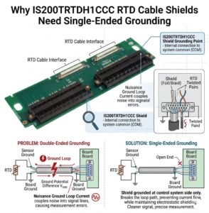
Analyzing Grounding Pitfalls and Compliance with Industry Standards
Incorrect shield termination often compromises even the highest quality factory automation systems. For instance, grounding both ends of a feedback cable shield creates destructive ground loop currents. This common-mode noise often surpasses the original EMI radiating from adjacent power cables. Field technicians must terminate the shield at a single point, specifically at the turbine control system cabinet side. Adhering to the IEC 61000 standard ensures robust electromagnetic compatibility across the entire plant network.
Diagnosing Control Loop Instability via Advanced Trend Analysis
Induced noise in an LVDT circuit frequently mimics mechanical actuator failures or hydraulic component wear. Consequently, maintenance teams waste valuable downtime replacing functional servo valves or transducers unnecessarily. At PLC Pioneer, we routinely advise engineers to isolate the control network signatures before swapping hardware. You can identify electrical interference easily by monitoring the valve command against actual coil current feedback using a high-speed portable oscilloscope.
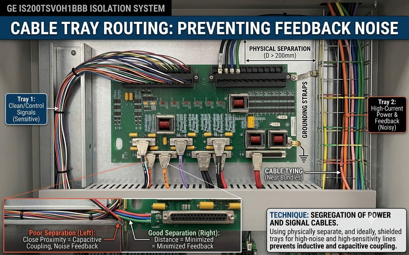
Best Practices for Physical Cable Separation and Noise Mitigation
To eliminate cross-talk in dense cable trays, field installation teams must enforce strict physical segregation rules. For standard AC power cables, maintain a minimum physical clearance of 300 mm (12 inches). For high-frequency VFD output cables, increase this isolation distance to at least 600 mm (24 inches). If a shared cable tray is unavoidable, install a continuous, grounded metallic barrier to shield the sensitive instrumentation wires.
Procurement Guide: Specifying Hardware for Critical Control Upgrades
The IS200TSVOH1BBB requires specialized wiring strategies that differ substantially from standard digital I/O modules. When purchasing replacement boards for legacy gas or steam turbine retrofits, procurement officers must include mandatory twisted-pair shielded instrumentation cables. Additionally, you should verify the exact hardware revision level of your existing turbine control panels. Certain older configurations require firmware updates to ensure full compatibility and noise immunity.
—
Field Installation Checklist & Technical Requirements
- ✅ Verify Shielding: Ensure 100% continuous coverage using high-grade twisted-pair instrumentation cables.
- ⚙️ Enforce Isolation: Separate low-voltage analog signal wires from heavy motor feeders using distinct metallic conduits.
- 🔧 Implement Suppression: Install external surge suppressors on the power lines feeding the primary servo terminal boards.
- 📊 Establish Baselines: Record baseline signal-to-noise ratios during the initial plant commissioning phase.
—
PLC Pioneer’s Technical Commentary
“Throughout my years optimizing power generation control systems, I have noticed that installation shortcuts cause most intermittent faults. Many technicians blame the controller or the servo valve for hunting issues. However, the root cause is almost always unshielded wiring sharing space with high-voltage lines. In 2026, modern digital architectures demand clean data. Protecting your analog feedback loops from day one is the most cost-effective way to prevent forced outages.” — PLC Pioneer
Frequently Asked Questions
Q: How can field technicians distinguish between mechanical valve stickiness and electrical noise?
Analyze the valve command trend against the feedback loop signature. Mechanical binding causes a distinct step-like response or time delay, whereas electrical interference appears as high-frequency, random micro-oscillations while the valve is stationary.
Q: Does the use of armored cable eliminate the need for distinct tray routing?
No, armor reduces magnetic field coupling but does not eliminate it entirely. You must still maintain physical separation gaps between analog measurement cables and high-power conductors to prevent signal degradation.
Q: What is the most effective method to resolve a ground loop on a turbine control board?
Isolate the feedback cable shield at the field element side entirely. Ensure the shield connects to ground only at the dedicated terminal block inside the control cabinet enclosure.
—
Industrial Application Scenario: Power Plant Retrofit Success
A combined-cycle power plant experienced severe load swinging on its main gas turbine fuel gas valve. The system frequently triggered alarms due to position feedback mismatches exceeding 0.8%. Our field audit revealed that the LVDT wiring shared a common unshielded cable tray with a 480V AC lube oil pump motor feeder. After rerouting the feedback cables into a dedicated, grounded steel conduit, the signal error dropped to less than 0.05%, stabilizing the turbine control loop immediately.
If you need to optimize your turbine control loops or source certified heavy-duty automation components, explore our technical inventory today.
Visit our official resource center for technical guides and hardware support: PLC Pioneer Limited