GE IS200STCIH2A Terminal Board: Onboard MOV Protection Limits Against High-Voltage Intrusion
The GE IS200STCIH2A discrete signal terminal board interfaces field contacts with Mark VI DCS and EX2100 control systems. Heavy industrial environments expose these boards to significant electrical disturbances. Consequently, understanding the built-in protection limits is essential for plant reliability. This technical analysis evaluates the true capabilities of the onboard Metal Oxide Varistor (MOV) against severe overvoltage faults.
The Role of Board-Level Components in Factory Automation
Field wiring in power generation and petrochemical facilities often runs parallel to high-energy cabling. This proximity exposes sensitive control systems to transient overvoltage threats. While the IS200STCIH2A utilizes an onboard MOV as an immediate shield, engineers must realize its constraints. It dampens microsecond-level spikes but cannot withstand prolonged high-voltage exposure without sacrificial failure.
Evaluating Transient Overvoltage Absorption Capabilities
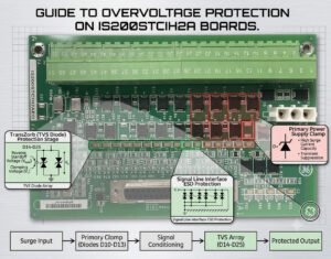
The onboard MOV effectively suppresses short-duration voltage spikes caused by inductive load switching and nearby lightning strikes. When a transient exceeds the clamping threshold, the MOV transitions rapidly to a low-resistance state. This action safely diverts the destructive energy away from critical input conditioning circuitry. Therefore, the component prevents false digital status changes and unexpected turbine trips during routine switching operations.
The Realities of Sustained High-Voltage Faults
A frequent error during field commissioning involves accidental cross-wiring with 120 VAC or 230 VAC control lines. A low-voltage discrete input channel cannot handle this continuous thermal energy. The MOV will clamp initially but will overheat within milliseconds. Consequently, the component fails short-circuit, or the printed circuit board traces burn open like a fuse.
Mitigating Electromagnetic Interference in Harsh Environments
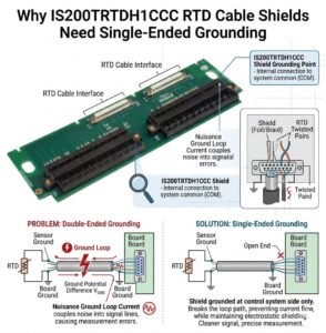
Large variable frequency drives (VFDs) and compressor motors generate immense electrical noise. The onboard MOV works alongside grounding structures to filter out conducted electromagnetic interference (EMI). This shielding ensures stable signal acquisition for critical turbine permissives and safety interlocks. As a result, the plant avoids the costly production losses associated with nuisance alarms and false shutdowns.
Best Practices for Industrial Control Systems Protection
To ensure maximum uptime, installation teams must implement a layered mitigation strategy. The integrated MOV serves as secondary defense rather than primary surge containment. We recommend installing external, DIN-rail mounted surge protection devices (SPDs) upstream for long outdoor cable runs. Additionally, technicians must verify all field voltages before landing conductors on the terminal board.
Pre-Commissioning Voltage Validation and Inspection
Field experience indicates that human error causes the majority of early-stage board failures. Therefore, checking input voltages during major turnarounds protects your hardware investment. Technicians should visually inspect the IS200STCIH2A after severe electrical storms or ground faults. Look closely for cracked varistor bodies, discoloration, or localized burn marks on the board surface.
—
Technical Implementation Checklist
- ✅ Upstream SPDs: Install dedicated primary surge suppressors for field wiring originating outside the control room.
- ⚙️ Pre-Wire Testing: Always measure incoming voltage before connecting field wires to terminal blocks.
- 🔧 Post-Incident Audit: Check the physical condition of the varistor following any major switchgear fault.
- 📊 Revision Verification: Confirm specific firmware compatibility and connector assignments prior to board installation.
—
PLC Pioneer Expert Commentary
“Many plant managers treat onboard MOVs as an absolute shield against wiring errors. In our fieldwork at PLC Pioneer, we routinely see destroyed input channels because someone mixed up 24 VDC inputs with 120 VAC interrogation loops. In 2026, maintaining hardware redundancy and enforcing strict testing isolation remains the only way to safeguard complex DCS infrastructure.” — PLC Pioneer
Technical Troubleshooting FAQ
Q: Does a blown varistor require immediate replacement of the entire terminal board?
Not always, but critical power facilities prefer complete board replacement to eliminate micro-crack risks. If the surge energy was limited, specialized repair facilities can replace the component. However, you must perform full validation testing before re-commissioning the system on a critical turbine line.
Q: How do we differentiate between transient damage and a sustained overvoltage failure?
Transient damage typically results in a clean, shorted component without severe carbon tracking. Conversely, a sustained 120/230 VAC cross-wire creates catastrophic thermal stress. This cross-wiring melts the interior elements, blisters the PCB laminate, and often vaporizes adjacent copper traces.
Q: Can we upgrade the onboard MOV to a higher energy rating?
Modifying the board directly violates the original equipment manufacturer specifications and voids industrial certifications. If your application demands higher energy handling, you should introduce external isolation relays or external barrier blocks instead of altering the internal components.
—
Solution Scenario: Elimination of Cross-Talk in Turbine Auxiliaries
A combined-cycle power plant experienced intermittent digital input faults on its turbine lubrication skid. Investigation revealed that unshielded AC pump cabling induced high-voltage spikes onto the 24 VDC signal lines. While the IS200STCIH2A MOVs clamped the spikes, the continuous stress caused channel degradation. Installing external isolation barriers successfully resolved the issue, reducing channel failures to zero.
If you need high-reliability boards, replacement modules, or expert hardware advice to secure your critical control loops, please browse our verified inventory.
Visit our official resource center for technical specification sheets and component support: PLC Pioneer Limited