GE Mark VI IS200TRLYH1B Suffix Breakdown: Decoding BFD, BED, and BGF Relay Configurations
The GE IS200TRLYH1B Relay Output Board serves as a cornerstone for dry-contact relay execution within heavy industrial automation. Turbines, excitation systems, and large-scale industrial control systems rely heavily on this module to manage critical signaling. Crucially, the board isolates sensitive control logic from harsh field device environments, ensuring dependable command execution for interlocks and emergency shutdowns.
The Operational Weight of Relay Output Reliability
In power generation, oil and gas, and process industries, plant availability hinges entirely on the integrity of relay outputs. A single component failure can freeze a critical breaker operation or disrupt an automated protection sequence. Consequently, unexpected downtime can ripple through a facility, inducing massive financial losses. Hardware reliability at this level directly dictates overall factory automation efficiency and operational safety.
Technical Synchronization: Galvanic Isolation Capabilities
The IS200TRLYH1B excels at providing robust galvanic isolation between the core control processor and external field circuits. From an engineering perspective, this boundary prevents dangerous voltage transients and ground loops from invading the Mark VI or EX2100 controller backplane. As a result, users notice a significant reduction in erratic controller faults during large motor startups or major switching events.
Evaluating Contact Wear and Switching Lifespans
Engineers typically deploy these relay boards for high-stakes tasks like emergency shutdown signals and breaker control. However, inductive loads like heavy contactor coils accelerate mechanical wear and erode contact surfaces over time. At PLC Pioneer, we always remind field technicians to evaluate real-world switching frequency rather than relying solely on abstract nominal ratings. Without adequate arc suppression, inductive spikes will rapidly shorten relay service life.
System Compatibility Within Advanced Control Platforms
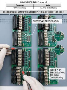
The entire IS200TRLYH1B family interfaces directly with proprietary GE turbine and excitation control architectures. When dealing with suffix variations like BFD, BED, or BGF, compatibility depends on precise hardware revision history and firmware database versions. These suffixes generally represent internal manufacturing updates rather than modifications to the base relay count or voltage thresholds. Therefore, maintaining updated hardware databases prevents unexpected mismatch errors during critical maintenance windows.
Proactive Installation Practices: Network and Mechanical Stability
Field experience indicates that physical environment factors cause a high percentage of industrial control systems failures. For instance, severe vibrations on gas turbine skids or offshore platforms can gradually back out terminal screws over months of operation. Technicians must enforce exact OEM torque specifications on all field wiring during annual outages. In addition, proper cable strain relief protects the physical terminal blocks from long-term mechanical fatigue.
Suppression Strategies for Inductive Field Devices
Driving unsuppressed solenoids or auxiliary relays from a TRLY board introduces massive electromagnetic interference into local wire runs. To combat this, install external surge suppression devices such as RC snubbers or metal oxide varistors (MOVs) directly across the load. This simple addition dampens voltage spikes, preserves contact gap integrity, and extends board lifespan significantly. Ultimately, proactive physical hardening prevents erratic software troubleshooting down the line.
—
Implementation Checklist & Maintenance Insights
- ✅ Torque Audits: Verify terminal retention metrics annually to prevent localized overheating from loose connections.
- ⚙️ Arc Suppression: Fit external flyback diodes or snubbers on all inductive DC loops connected to the board.
- 🔧 Revision Matching: Cross-reference your system software configuration before swapping suffix variants mid-outage.
- 📊 Vibration Isolation: Inspect mounting hardware integrity if deploying the panel near high-vibration compressor trains.
—
PLC Pioneer’s Expert Commentary
“Throughout our years of servicing DCS and turbine control environments, suffix confusion remains a constant headache for procurement teams. Many operators assume a change from BED to BGF indicates a shift in voltage capability or terminal layout, leading to unnecessary sourcing delays. In reality, GE utilizes these trailing letters for internal bill-of-materials traceability and component lifecycle management. The core schematic remains consistent across the family, though firmware validation rules may apply depending on your specific Mark VI core software revision.” — PLC Pioneer
Frequently Asked Questions
Q: How do field technicians diagnose an intermittent relay failure on a TRLY board without interrupting live processes?
Technicians should utilize the diagnostic LEDs on the board to check the command state against physical continuity at the terminal block. If the logic indicator activates but the field circuit fails to close, contact pitting or localized mechanical binding has likely occurred inside the relay casing.
Q: Does mixing different suffix revisions on the same termination rack cause signal propagation delays?
No, because the underlying mechanical relays and driver circuits share identical timing specifications across these revisions. Signal latency variations are practically nonexistent; however, ensure your system software configuration file recognizes the physical hardware revision to avoid nuisance system alarms.
Q: What is the most effective method to clean contact contamination caused by atmospheric outgassing?
Use a high-purity, non-residue electronic contact cleaner along with lint-free swabs during a scheduled system outage. Never use abrasive materials on these specialized relay contacts, as removing the microscopic precious-metal plating will trigger permanent contact oxidation.
—
Application Scenario: Excitation System Retrofits
Consider a large utility generator undergoing a control system migration where an older revision board needs replacement. Installing an IS200TRLYH1BGF module ensures that critical emergency trip chains retain complete galvanic isolation from high-voltage field exciters. By mapping the diagnostic registers accurately within the control system, operators can view real-world trip states instantly, avoiding blind spots during grid synchronization anomalies.
If you need to source specific hardware revisions or require verified components to maintain your turbine control systems, check our extensive inventory of certified spare parts.
Visit our official resource center for technical support and product documentation: PLC Pioneer Limited