Does Thermal Deformation of IS200EDEXG1BQ Resistors and MOVs Compromise Overvoltage Protection?
The GE IS200EDEXG1BQ de-excitation board serves as a foundational safety barrier within the EX2100 excitation control systems. This critical control board handles the rapid dissipation of stored magnetic energy when a generator field de-excitation event triggers. Consequently, it shields delicate electronic sub-systems and thyristor bridges from destructive transient overvoltage spikes during sudden faults.
In high-capacity power plants, petrochemical facilities, and heavy industrial automation environments, a failure in this circuit can paralyze production. Unstable overvoltage protection compromises generator availability and drives up emergency maintenance expenses. Therefore, ensuring the absolute physical and electrical integrity of the board’s heavy-duty linear resistors and Metal Oxide Varistors (MOVs) remains paramount.

MOV Clamping Instability Under Prolonged Thermal Stress
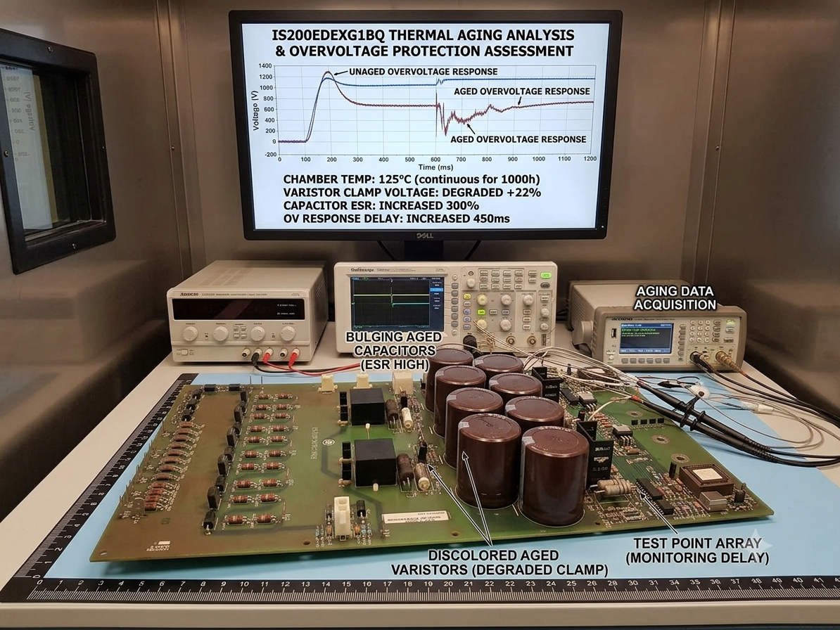
Metal Oxide Varistors function as voltage-dependent clamps, shifting from a high-resistance state to a highly conductive path during line surges. However, field data reveals that continuous operation at elevated system temperatures drastically accelerates zinc oxide grain boundary degradation inside the MOV. As structural damage accumulates, the device experiences a sharp spike in leakage current and a severe reduction in surge absorption limits.
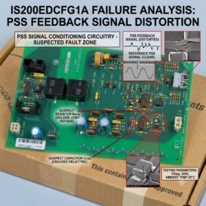
Physical clues like casing distortion, blistering, or solder joint discoloration on the IS200EDEXG1BQ signal that the protection window has warped. For instance, an aged varistor might clamp well below the designed safety margin, triggering frequent nuisance trips. Alternatively, the clamping voltage may drift higher, exposing downstream gate drivers and control networks to dangerous voltage overshoot before firing.
The Destructive Impact of High-Power Resistor Thermal Drift
The field de-excitation loop relies heavily on precision resistor banks to absorb and discharge immense inductive loads safely. When these power resistors constantly function near their thermal boundaries, they suffer from micro-cracking, solder fatigue, and baseline resistance drift. According to general power engineering standards, even a minor variance of five percent will alter the field current decay trajectory entirely.
While a shifting resistance value does not modify the physical properties of an adjacent MOV, it alters circuit energy dynamics. A degraded resistor branch sheds less energy, forcing the companion varistor to absorb a higher percentage of the total inductive dump. Therefore, uncorrected resistor aging creates a cascading failure chain that directly threatens the entire overvoltage protection network.
Cabinet Environment and Accelerating Component Wear Lifecycles
The microclimate surrounding your industrial control hardware dictates the true operational lifespan of heavy-duty power components. This risk escalates inside high-temperature settings like gas turbine auxiliary enclosures, steam turbine decks, and unventilated electrical control rooms. In my extensive engineering work with PLC Pioneer, local hot spots around de-excitation resistors often register 30 to 50 degrees Celsius higher than ambient cabinet readings.
Industry research derived from the IEEE 1415 standard indicates that operating semiconductors and passives above rated thermal baselines halves their operational lifespan. As a result, physical deformation of board components is never just an aesthetic flaw. Instead, it serves as a distinct warning that cumulative thermal fatigue has compromised the system’s electrical response thresholds.
—
Proactive Maintenance Checklist & Thermal Control Guidelines
- ✅ **Execute Periodic Thermography:** Scan the de-excitation panel under full-load operation to detect asymmetrical heating across parallel resistor links.
- ⚙️ **Quantify Leakage Currents:** Measure MOV leakage current and insulation resistance metrics during scheduled turbine outages to catch silent insulation failures.
- 🔧 **Enforce Environmental Control:** Clean cabinet filters and verify cooling fan cfm ratings to isolate high-heat power panels from sensitive control networks.
- 📊 **Track Resistance Baselines:** Audit and log precision resistor ohmic values annually, replacing any modules that drift past original manufacturer specifications.
—
PLC Pioneer’s Field Technical Commentary
“Throughout years of auditing excitation cabinets, I have watched many maintenance teams dismiss minor resistor discoloration or slight MOV bubbling. This oversight is a critical mistake in factory automation because protection components do not give warning before catastrophic breakdown. In modern heavy power systems, waiting for a hard alarm to signal component wear usually results in blown thyristors and days of forced downtime. Proactive renewal is always the cheaper route.” — PLC Pioneer
Frequently Asked Questions Regarding Excitation Safety
Q: What causes a de-excitation board component to fail during standard, non-fault generator operations?
Continuous low-level harmonic distortion and subtle leakage currents create a baseline thermal load that slowly cooks the component substrate. Over time, this constant heat accumulation induces structural breakdown without requiring a major transient surge event to spark the failure.
Q: Can third-party component replacement restore a deformed IS200EDEXG1BQ board back to factory specifications?
Component level repair is possible but carries immense risk because factory-matched tolerances dictate the exact energy sharing profiles. Utilizing components with mismatched thermal coefficients can imbalance parallel paths, leading to localized overheating and premature board destruction.
Q: How do environmental pollutants like oil mist or chemical gases interact with thermally stressed boards?
High heat compromises the outer protective epoxy coatings of varistors and resistors, leaving them vulnerable to airborne moisture and corrosive chemicals. This exposure leads to surface tracking, flashovers, and sudden phase-to-ground faults inside the industrial control system cabinet.
—
Application Scenario: Generator Field Overvoltage Mitigation
Consider a large scale manufacturing facility utilizing a traditional EX2100 setup with an undiagnosed, thermally degraded de-excitation card. During a routine grid disconnect fault, the main breaker trips, forcing the field winding to dump its immense inductive energy. Because the warped resistors cannot handle their design share and the aged MOVs clamp late, a severe voltage spike punctures the thyristor gate layers, leading to complete system shutdown.
If you need to source authentic, high-reliability replacement boards or require field-proven hardware to reinforce your turbine protection setups, explore our extensive inventory of genuine industrial control solutions.
Visit our official resource center for technical guides and hardware support: PLC Pioneer Limited